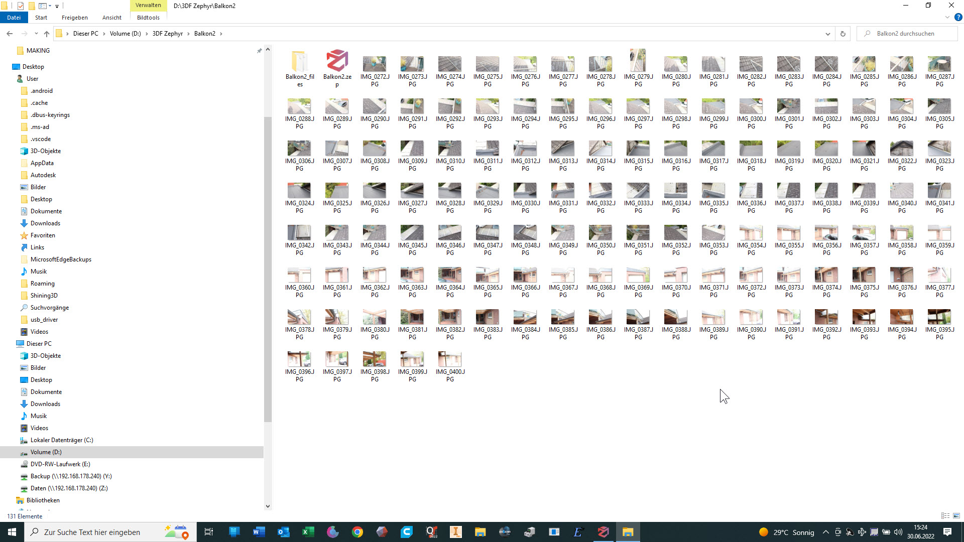
- Schritt: Fotos machen und in 3DF-Zephyr bearbeiten (Mein 3D-Scanner ist für solche großen Objekte nicht ausgelegt). Es entsteht eine dreidimensionale Datei im obj-Format, die zu groß ist, um sie hier oder auf sketchfab hochzuladen.
(hier ein Link zu einem früheren Upload aus weniger Bildern und mitsamt der umliegenden Botanik: https://sketchfab.com/3d-models/platz-fur-ubergang-zum-garagendach-befc28424f9a4092b63082d51d1c8e50)
1st Step: Take photos and process them in 3DF-Zephyr (my 3D scanner is not designed for such large objects). The result is a three-dimensional file in obj format that is too large to upload here or on sketchfab.
(here is a link to an earlier upload from fewer images and including the surrounding botany:https://sketchfab.com/3d-models/platz-fur-ubergang-zum-garagendach-befc28424f9a4092b63082d51d1c8e50
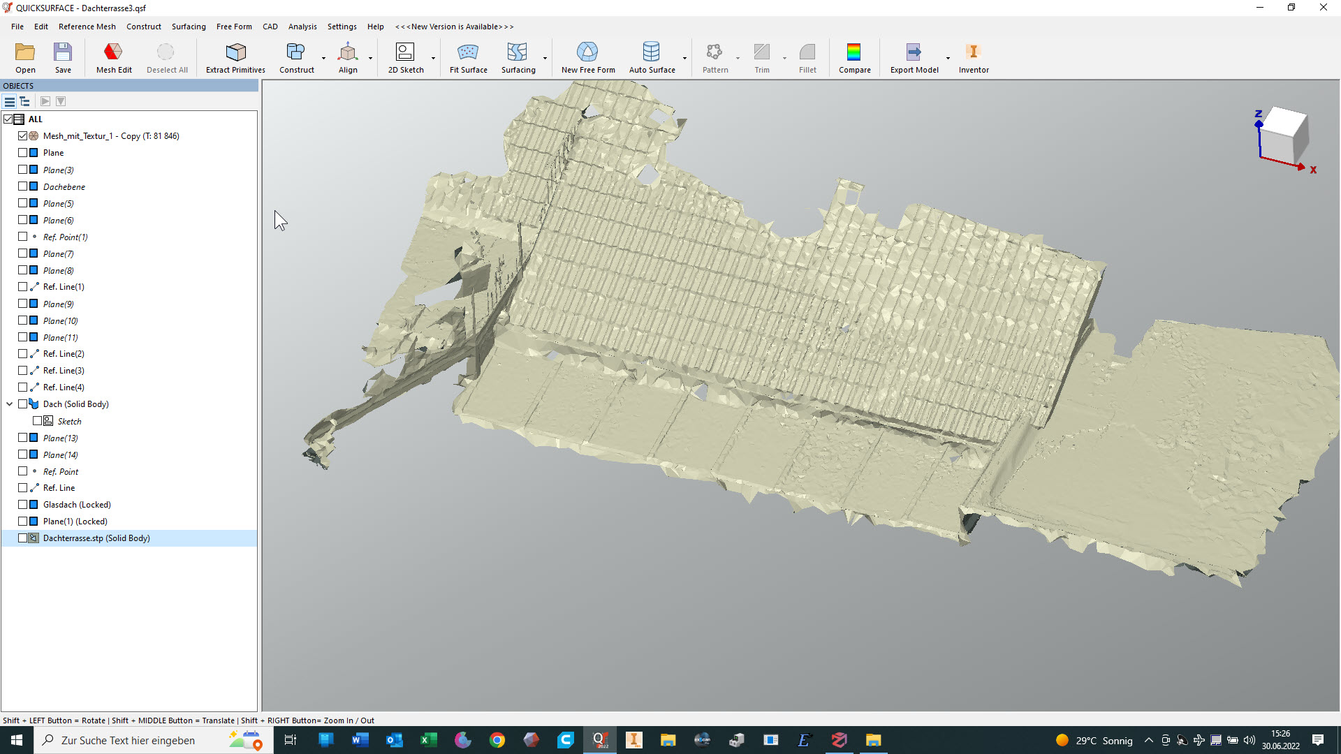
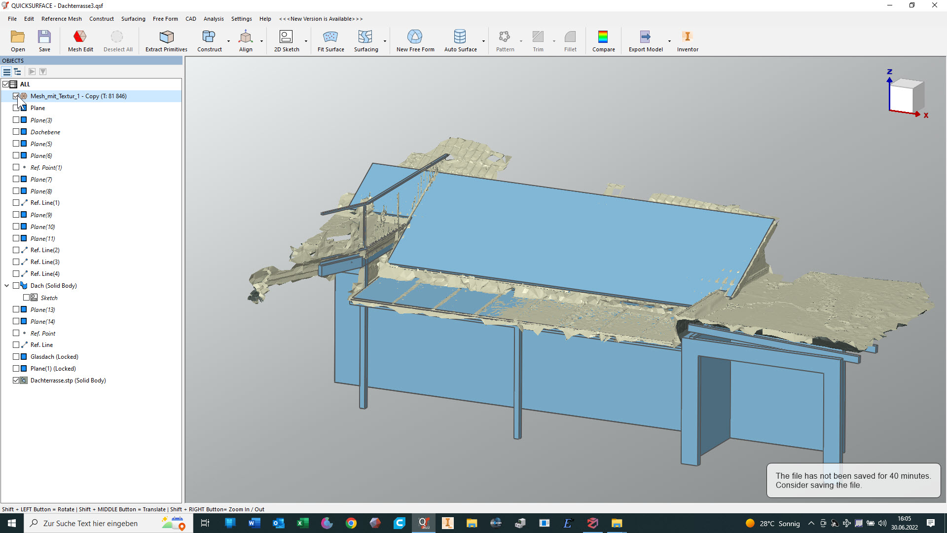
2. Schritt: Die OBJ-Datei in QuickSurface öffnen und die Auflösung reduzieren. Das sieht dann so aus:
Step 2: Open the OBJ file in QuickSurface and reduce the resolution. This then looks like this:
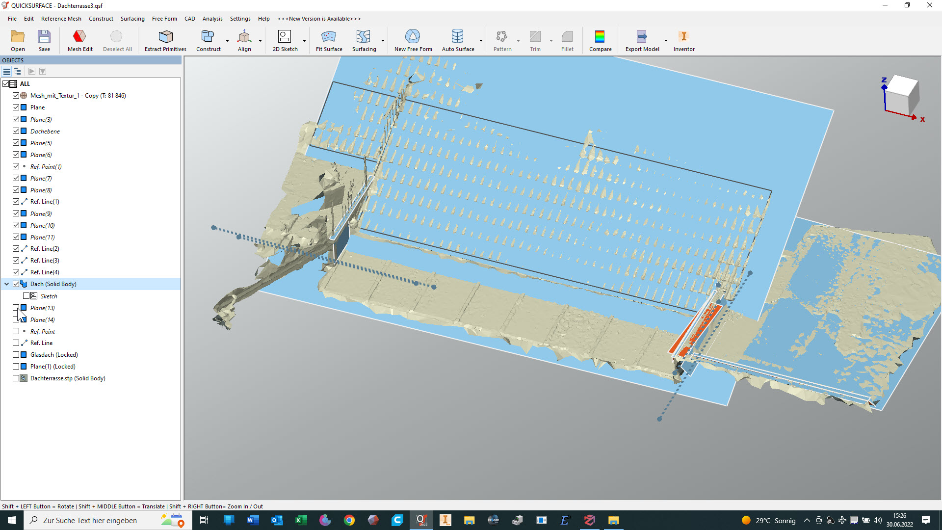
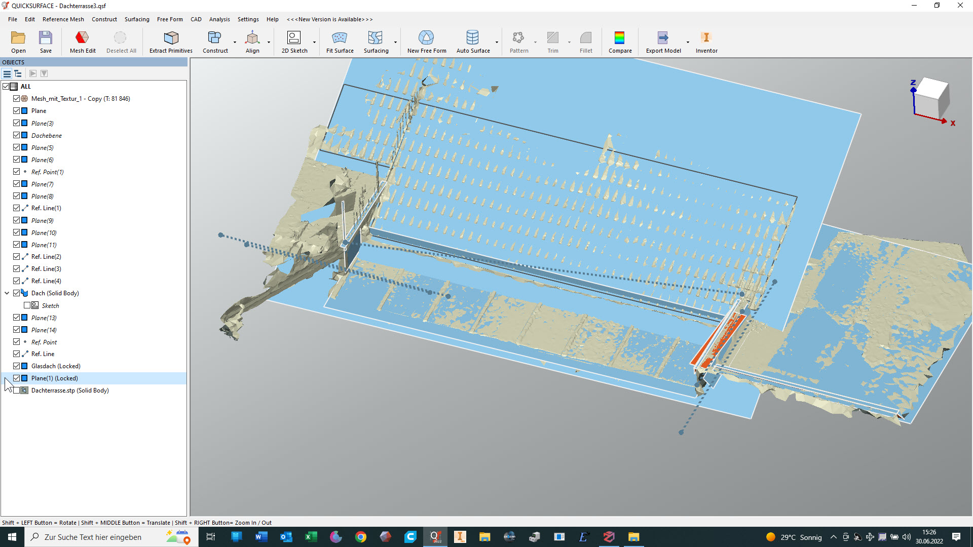
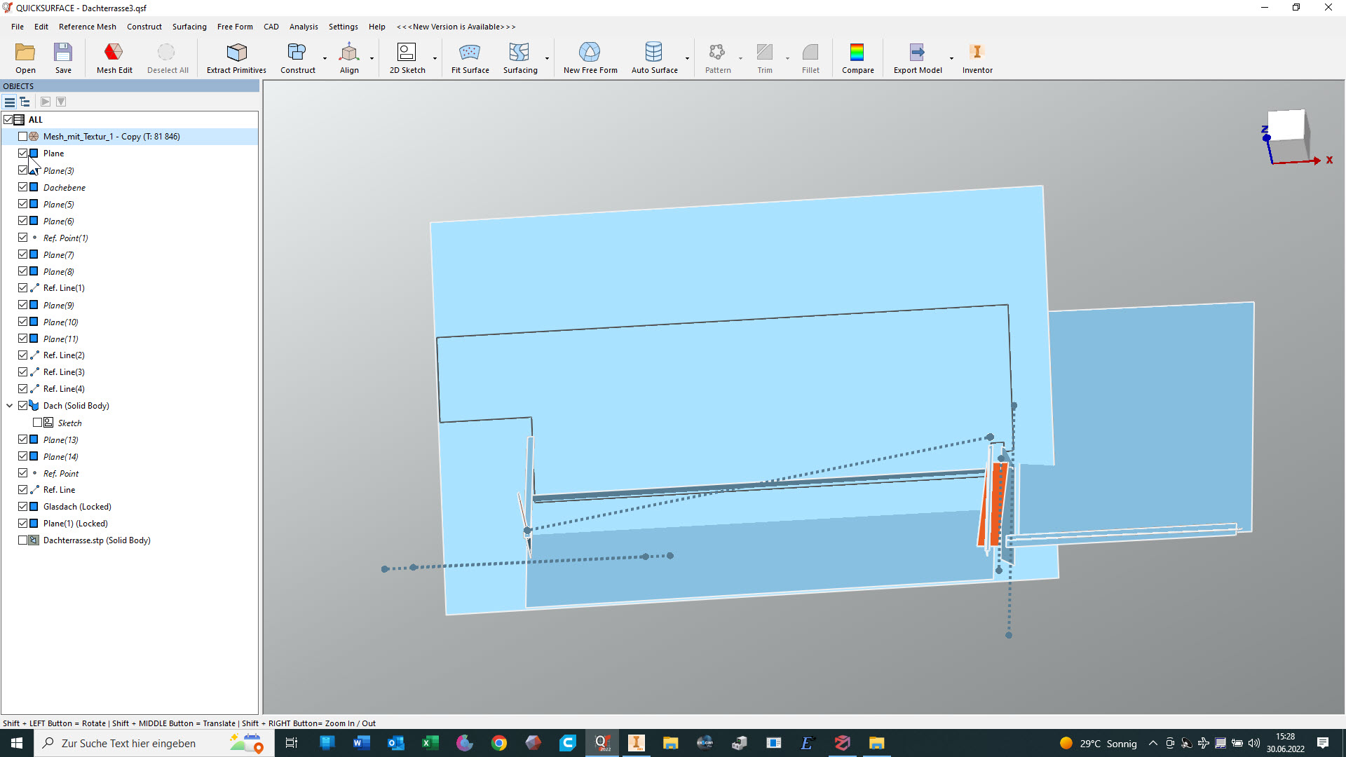
3. Schritt: Herausarbeiten einfacher geometrischer Strukturen wie Flächen, Kegel, Zylinder usw. (in diesem Fall hauptsächlich Flächen)
Step 3: Working out simple geometric structures such as planes, cones, cylinders, etc. (in this case mainly surfaces)
4. Schritt: Dann muss der Maßstab noch angepasst werden, weil 3DF-Zephyr überhaupt keine Vorstellung von den wirklichen Dimensionen hat (das schräge Kontrollmaß betrug übrigens ursprünglich 14,4 mm, musste also um den Faktor ~500 vergrößert werden)
Step 4: Then the scale still has to be adjusted, because 3DF-Zephyr has no idea at all of the real dimensions (by the way, the oblique control dimension was originally 14.4 mm, so it had to be enlarged by a factor of ~500).
Der Vergleich zeigt, ob ich eine weitgehende Übereinstimmung mit dem mesh erreicht habe:
The comparison shows whether I have achieved extensive agreement with the mesh:
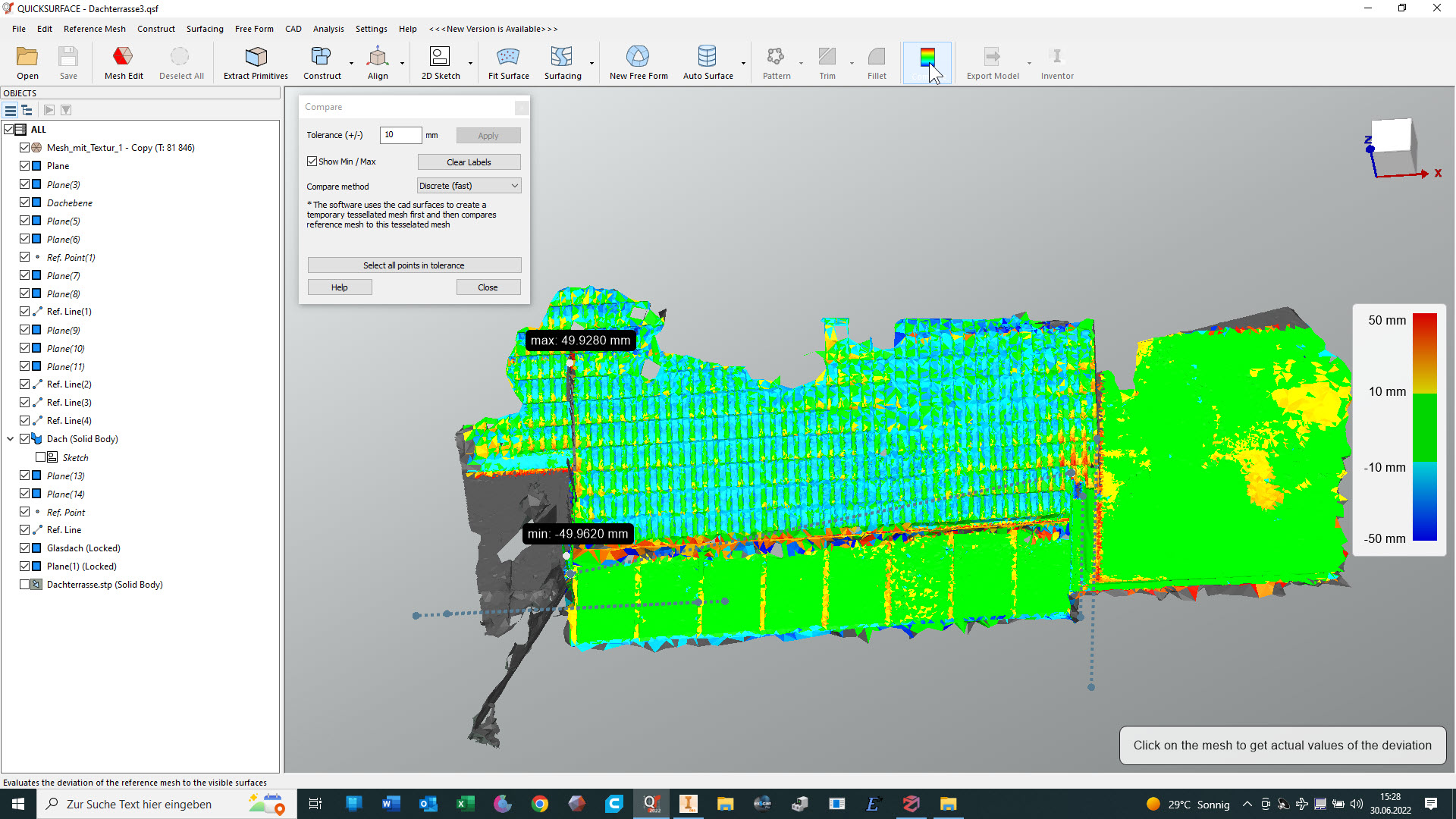
Es kann eine STEP-Datei an Inventor übergeben werden
A STEP file can be transferred to Inventor
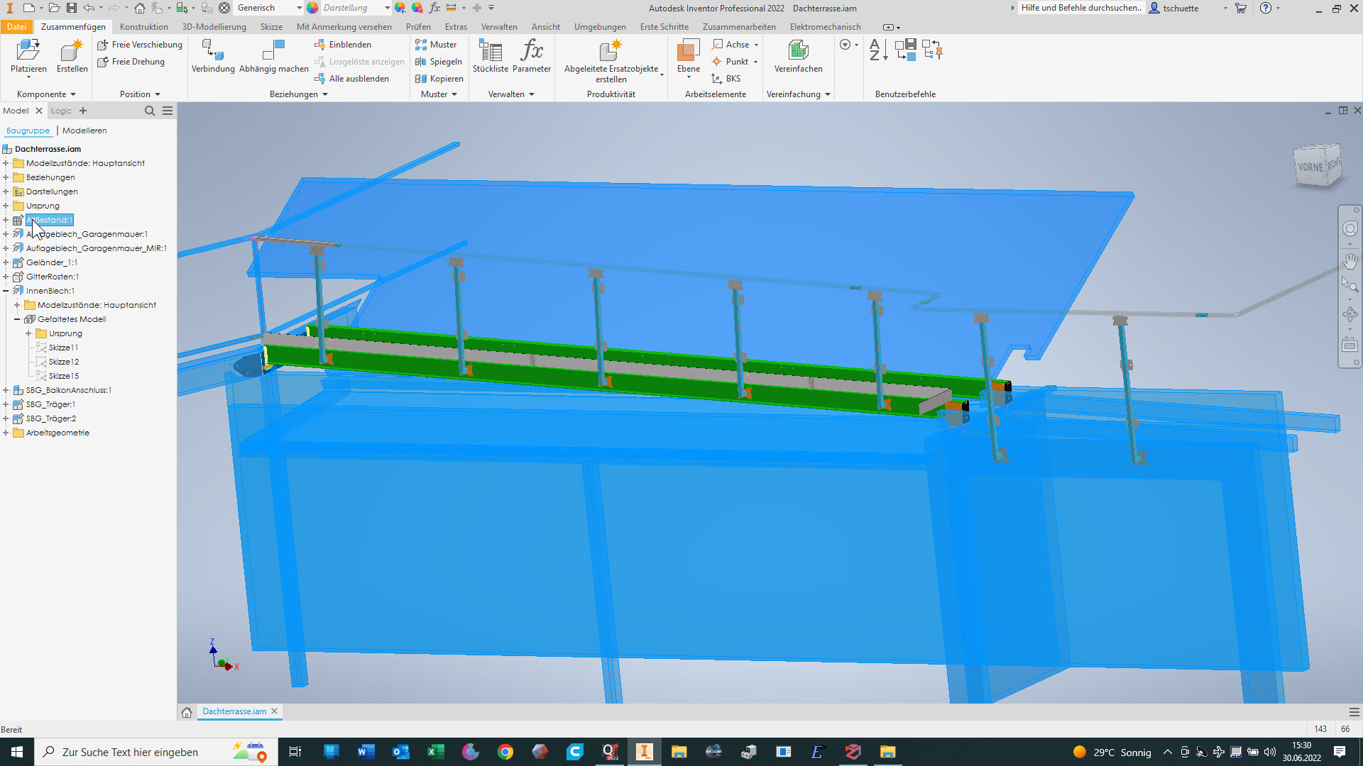
5. Schritt: Aufnehmen von Kontrollmaßen und Modellieren im Inventor. Die bisher erzeugte Störkontur dient hierbei fast nur zur Kontrolle. Die Winkel der Flächen zueinander habe ich aber als richtig angenommen.
Step 5: Recording control dimensions and modelling in Inventor. The interfering contour created so far serves almost only as a check. However, I have assumed that the angles of the surfaces to each other are correct.
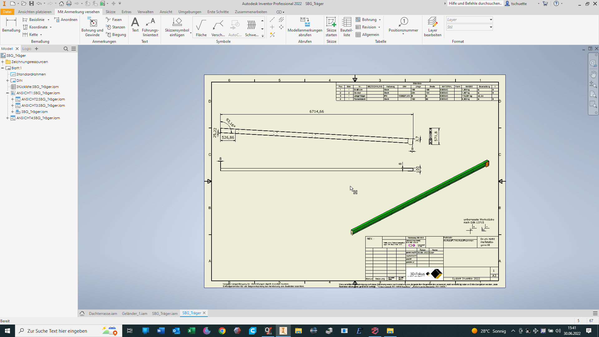
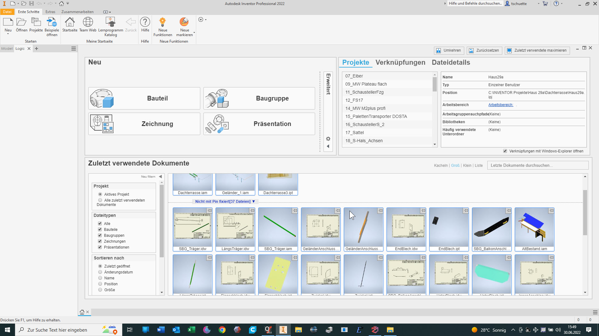
6. Schritt: Erzeugen von Ableitungen der erzeugten Bauteile und Baugruppen für die Fertigung
Step 6: Generate derivations of the created components and assemblies for production
Zum Spaß habe ich noch das Inventor-Modell als STEP-Datei exportiert und in QuickSurface mit dem mesh verglichen:
For fun, I exported the Inventor model as a STEP file and compared it with the mesh in QuickSurface:

Hier ist mir aufgefallen, dass ich die 2D-Zeichnung der Schweißbaugruppe für die Träger noch nicht erzeugt hatte :-S
Here I noticed that I had not yet created the 2D drawing of the welding assembly for the beams :-S